AI
BlenderProc's depth flag changes the measurement pipeline
A static audit of BlenderProc at 76bd8b8: activate_antialiasing swaps the Z pass for a range-mapped Mist path, and the inspected depth test is defined only for False.
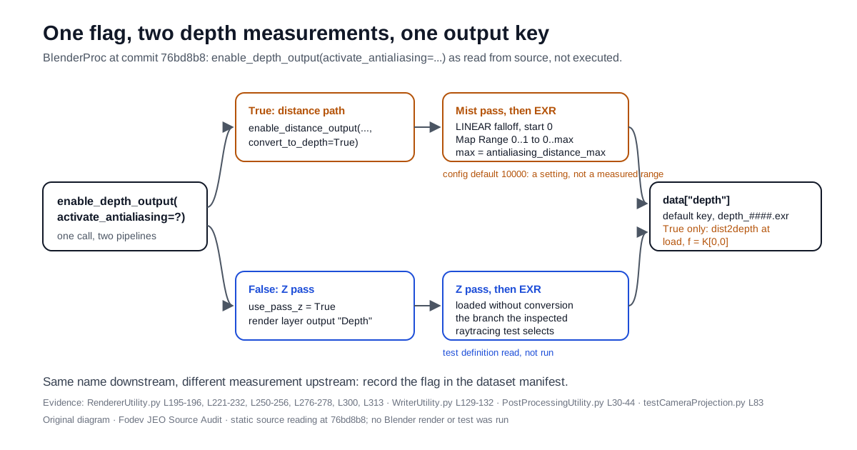
In BlenderProc, enable_depth_output(activate_antialiasing=True) is not a smoother copy of the same depth image. At the commit I read, the flag selects a different measurement pipeline. True renders Blender’s Mist pass over a configured range and converts the result from distance to depth when the file is loaded. False reads the Z pass directly. With default arguments both land under the same depth key with the same file names, and the one depth-equality test I inspected is defined only for False.
Scope, stated once and plainly. Static audit date: 2026-10-05. Pinned commit: 76bd8b82ee19489843578ff045298642197bf883, which was still main HEAD at retrieval; it was committed on 2026-01-07, and the repository’s last push was 2026-01-20. This is not news about a new release. I read source, tests, documentation and examples. I did not install Blender or BlenderProc, render a frame, or run a test, so nothing below is a benchmark, an accuracy figure, or a pass/fail result.
Throughout, I label four kinds of statement separately: source finding (what the pinned code does), test definition (what a test asserts, not whether it passes), proposal (a checklist I derived, not one I have run), and open question (untested).
Can a depth image get smoother without changing what it measures?
Synthetic RGB-D is attractive for 3D vision, robotics and game QA because the renderer holds the exact scene geometry. A rendered depth map can seed a point cloud, check that an occlusion test agrees with the scene, or provide labels a physical sensor cannot. The appeal is that the renderer knows the answer.
Antialiasing in an RGB image is a visual decision: blend the colours at an edge and the picture looks better. In a depth image, the same idea is less innocent. A pixel straddling the edge of a near object and a far wall has no single correct depth, and any blend is a modelling choice. So when a library offers activate_antialiasing on its depth output, I want to know what that switch actually changes. Is it a filter on the same quantity, or is it a different measurement?
The renderer tutorial gives a short answer: the distance output is antialiased, the depth output is the z-buffer “without any smoothing effects”. The source gives a more specific one, and it is the one your dataset inherits.
Technical Analysis: what the pinned source actually does
Source finding: one call, two pipelines
The fork is three lines in RendererUtility.py:
1
2
3
4
# blenderproc/python/renderer/RendererUtility.py @ 76bd8b8, lines 276-278 (GPL-3.0)
if activate_antialiasing:
    return enable_distance_output(activate_antialiasing, output_dir, file_prefix, output_key,
                                  antialiasing_distance_max, convert_to_depth=True)
On that branch, enable_distance_output sets the Mist pass to start at 0 with its depth equal to antialiasing_distance_max and a LINEAR falloff, enables use_pass_mist, and pushes the Mist output through a Map Range node that maps 0..1 onto 0..antialiasing_distance_max before writing an EXR. It registers the output with convert_to_depth: True. When the outputs are loaded, WriterUtility sees that flag and runs dist2depth on the array.
On the other branch, enable_depth_output enables use_pass_z, routes the render layer’s Depth output to the EXR, and registers no conversion. The mirror image also exists: enable_distance_output(activate_antialiasing=False) delegates to the Z-pass path with convert_to_distance=True.
| Source finding at 76bd8b8 | activate_antialiasing=False | activate_antialiasing=True |
|---|---|---|
| Blender pass | Z pass (use_pass_z, render-layer Depth) | Mist pass (use_pass_mist) |
| Range handling in BlenderProc code | none | Mist start 0, depth antialiasing_distance_max, LINEAR; Map Range 0..1 to 0..max |
| What BlenderProc treats the EXR as | planar depth | distance, converted on load |
| Conversion when loaded | none | dist2depth, focal length K[0,0] |
| Output key and file pattern (default arguments) | depth, depth_####.exr | depth, depth_####.exr |
| Named in the inspected depth-equality test definition | yes | no |
The last two rows are the practical problem. The registered entries differ only in an internal conversion flag, so a folder of depth_0000.exr files and a dictionary key called depth do not tell a downstream consumer which pipeline produced them. That is my inference from the registration code; I did not inspect EXR headers written by Blender.
One more source detail matters when you mix outputs. The two functions share global guards: turning on enable_depth_output(activate_antialiasing=True) and enable_distance_output(activate_antialiasing=True) in the same run raises a RuntimeError whose message tells you to derive the second image with dist2depth or depth2dist instead. If your pipeline needs both quantities from the antialiased path, that conversion is the route the error message itself recommends.
Distance versus depth, in plain terms
Distance is the length of the ray from the camera centre to the surface it hits. Depth is how far that hit point lies along the camera’s viewing axis. At the principal point (normally near the image centre) they coincide; away from it the ray is slanted, so distance is larger than depth for the same point.
dist2depth converts between them with the pinhole model: it reads the intrinsics K, takes K[0,0] as the focal length f and (K[0,2], K[1,2]) as the principal point, and computes depth = dist * f / sqrt(x_opt**2 + y_opt**2 + f**2) per pixel, where x_opt and y_opt are the pixel’s offsets from the principal point. That is a clean, deterministic step, and it means the True path’s output is only as right as the K that exists when you load it.
There is a narrower point here that I want to state carefully. The function’s own derivation comment uses a single f0 for both axes, while BlenderProc’s intrinsics code supports unequal fx and fy by changing the pixel aspect ratio (fy = fx / pixel_aspect_ratio). By that derivation, the conversion is exact only when fx equals fy. That is an inference from the formula, not a measured error: I did not render an anisotropic camera, and I do not know how large the effect would be in practice.
Source finding: the range is a setting, not a specification
DefaultConfig.py sets antialiasing_distance_max = 10000. The code attaches no unit and no accuracy promise to it; the docstring describes it as the “Max distance in which the distance is measured” and adds “Resolution decreases antiproportionally.” So the parameter trades range against resolution by its author’s own description, and how much resolution you actually get depends on Blender’s Mist computation and the EXR’s precision, neither of which I measured. Please do not read the default as “10 metres”, “10 kilometres”, or a guaranteed working range.
The same file lists a camera clip_end = 1000. I did not trace where that value is applied or whether it interacts with the Mist range, so it appears below only as an open question.
Test definition: what the inspected test pins down, and what it does not
tests/testCameraProjection.py defines test_depth_via_raytracing. It places a camera at 640x480 over the bundled scene, computes a reference depth image by BVH raytracing, then renders depth with enable_depth_output(activate_antialiasing=False). It maps rendered values >= 65504 to infinity, and over the pixels where the raytraced depth is finite it asserts that the median absolute difference is below 1e-4 and that more than 99% of differences are below 1e-4.
That is a tight agreement target for the Z-pass branch. I did not run it, so I make no claim about whether it passes today. I also searched only that test file for depth-equality assertions, so I am not claiming no other test exists. What I can say from the definition is narrower: it says nothing about the True branch, which goes through a different pass, a configured range and a post-load conversion.
If that shape sounds familiar, it is the one I found in mjlab’s CPU-only CI: a check that is honest about the path it runs, and a reader who assumes it covers the other path too.
The raytracing reference has its own conventions worth recording. depth_via_raytracing casts one ray per pixel, sets misses to infinity, and by default returns planar depth via the same dist2depth. unproject_points multiplies pixel coordinates by depth, applies the inverse of K, flips the y and z axes, transforms by the camera-to-world pose, and sets any point whose depth exceeds depth_cut_off (default 1e6) to NaN. So a ray miss becomes infinity in the depth image and NaN in the point cloud under the defaults.
The project’s own figures do not say which quantity they show
The basic example’s README embeds two composites, each showing an RGB render, a surface-normal image and a colour-mapped depth panel from one camera pose.
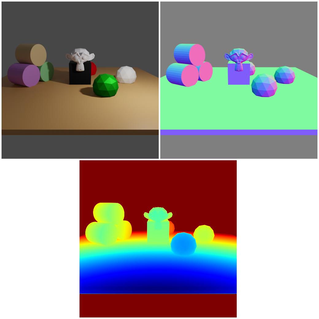
Three source facts frame this figure. The example’s current main.py requests enable_depth_output(activate_antialiasing=False). Its README prose still says the example generates “the normals and the distance” and lists distance_0000.exr files. And both basic-example images were last changed on 2021-09-17, while RendererUtility.py was last changed on 2024-12-12. The image files’ last-change date precedes the renderer source’s last-change date; it does not establish when the images were rendered.
Now a labelled inference. In the depth panel of Figure 1, the colour bands across the flat floor are curved arcs. For an ideal pinhole camera, planar depth on a flat plane produces straight lines of equal value in the image, while radial distance produces curves. So the panel looks consistent with a distance quantity rather than the Z pass the current example code asks for. I did not decode any values, the panel is a colour-mapped JPEG, and I cannot tell which code version rendered it. The point is not that the figure is wrong. The point is that even the project’s reference image cannot tell you which measurement you are looking at; only a recorded setting can.
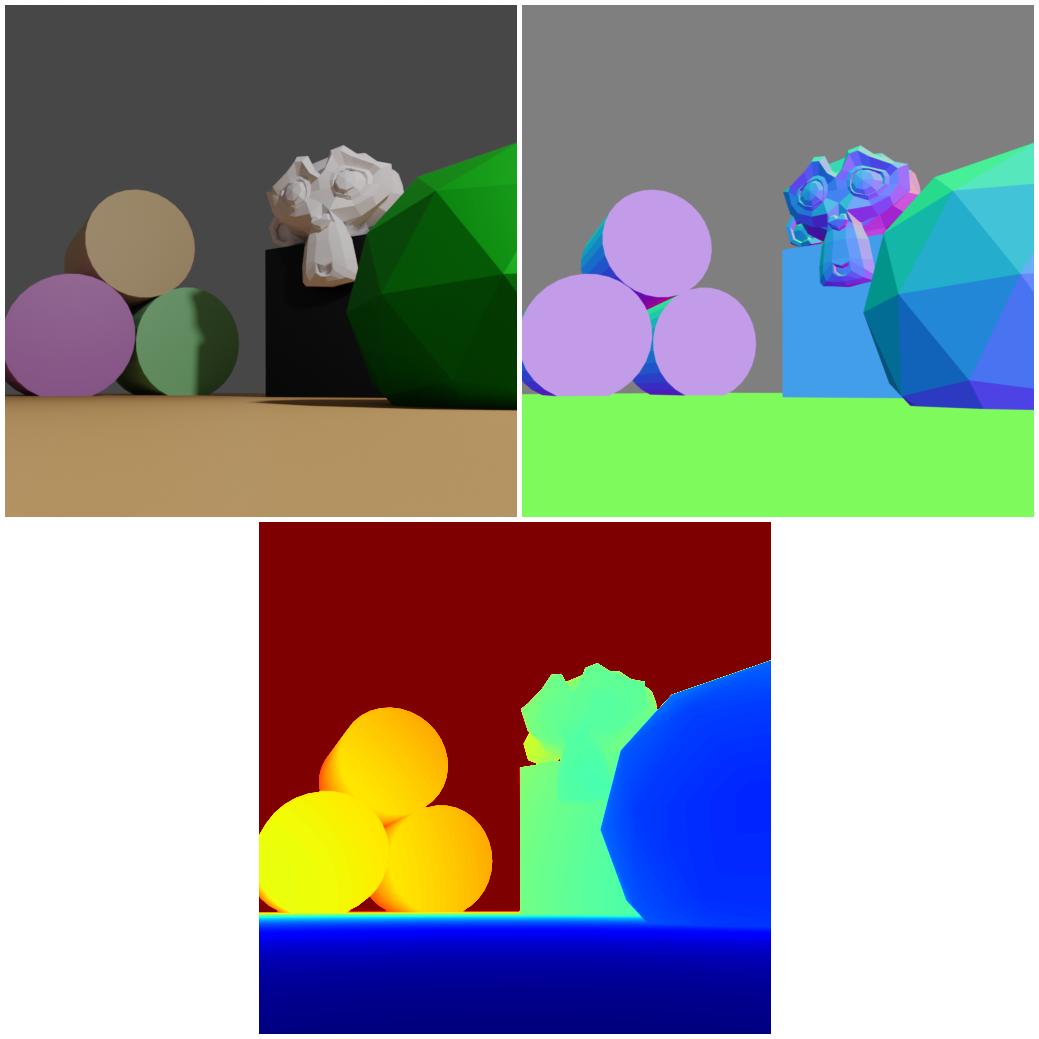
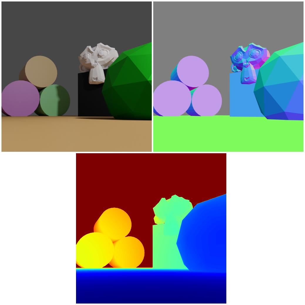
Figure 2 is the reason a depth file without its pose is half a datum. Both examples load the bundled scene.obj and camera_positions resources, and each frame’s depth only becomes geometry once you know which camera-to-world pose and which K it belongs to. This is the same question HyperFrames forced about “same video”: before you compare two renders, decide what unit equality is asserted in.
Record the measurement, not just the file
Proposal: a depth manifest for every synthetic dataset
What follows is a proposal derived from the source reading above. I have not run it against a production pipeline, and the values shown are placeholders, not measurements.
1
2
3
4
5
6
7
8
9
10
11
12
13
14
15
16
# Proposed depth manifest for one BlenderProc dataset (a proposal, not a validated schema)
blenderproc_ref: 76bd8b82ee19489843578ff045298642197bf883
depth_call: enable_depth_output
activate_antialiasing: false            # false: Z pass. true: Mist pass + dist2depth on load
antialiasing_distance_max: null         # required when true; config default 10000 implies no unit
stored_quantity: planar_depth           # radial_distance if you call enable_distance_output
intrinsics: {fx: null, fy: null, cx: null, cy: null, width: null, height: null}
fx_equals_fy: true                      # dist2depth's derivation assumes one focal length
pose_convention: "cam2world per frame; unproject flips y and z after inverse K"
invalid_values:
  raytrace_miss: inf                    # depth_via_raytracing
  unproject_cutoff: 1.0e6               # depth > cutoff becomes NaN in the point cloud
  rendered_sentinel: ">= 65504 treated as inf in the inspected test only"
point_cloud:
  source_pose_index: null
  resolution_at_unprojection: null      # K is read from the resolution current at that moment
Three acceptance rules fall out of the same reading, and they are also proposals:
- Separate the gates. RGB visual quality and geometric validity are different acceptance criteria. A dataset can pass the first and fail the second, and the flag is named after the first.
- Test the branch you ship. If you ship
activate_antialiasing=True, the inspected Z-pass test definition is not evidence for your data. Re-derive a sample of frames by raytracing and compare on your branch, with your range and intrinsics, before calling the depth “ground truth”. - Refuse unlabelled depth. A consumer that receives
depth_####.exrwithout the manifest should treat the data as ambiguous rather than guess.
The game-QA connection is direct, and I will keep it modest because I have no production measurement to offer. If synthetic depth backs an occlusion or line-of-sight check, regenerating the dataset with the other flag is the kind of change that would go unnoticed in a diff of file names and keys. That is my expectation from the code, untested. It is the same boundary The Sealed Lighthouse drew between passing conformance checks and proving the property a team actually cares about.
Source finding: one point cloud, two camera poses
The point-cloud example is the clearest picture of a second boundary: a cloud computed from one depth image is a sample of what one camera saw, not the scene’s geometry.
The example sets the resolution to 128x128, computes raytraced depth for camera pose index 1, unprojects it with pointcloud_from_depth(depth, 1), turns the points into a mesh drawn as red dots, and only then switches to 512x512 to render. Its README says the cloud “is computed from the view of the second camera pose (right image)” and “contains one point per pixel”. The two images below therefore show the same cloud from two camera poses. They are not two reconstructions.
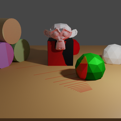
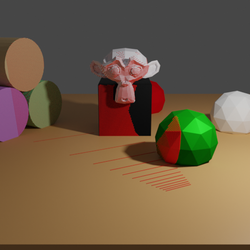
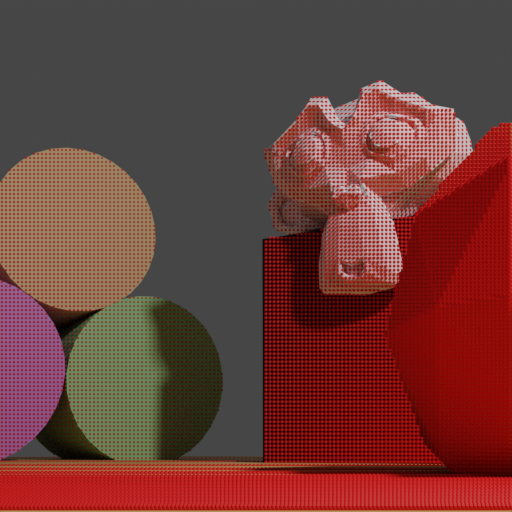
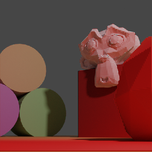
From the generating pose, the grid is regular and the surfaces look covered. From the other pose, only surfaces the generating camera could see carry points, the floor seen at a grazing angle breaks into separated lines, and the white sphere has none. Two more source details belong in the manifest. K is read from the scene’s current resolution, so in this example the unprojection uses the 128x128 intrinsics because it runs before the switch to 512x512; reorder those calls and you change the geometry. And background rays that miss become infinite depth, then NaN points under the default cutoff, so “number of points” depends on how much of the frame hits something.
Trade-offs, honestly
I cannot tell you which branch is better for your data, because I rendered neither. The False path is the one with an inspected equality test definition and no range parameter to choose. The True path is the one whose name promises antialiasing, at the cost of a configured range, a post-load conversion that depends on K, and no equality test definition among the files I read. Either can be the right choice; the wrong choice is not recording which one you made.
Rights and reuse of the four figures
Figures 1 to 4 are example images checked into DLR-RM/BlenderProc at commit 76bd8b8 and are conveyed here under that repository’s licence, the GNU General Public License v3. They are not covered by this site’s general content licence, they are not public domain, and the GPL is not an attribution-only licence. The pinned tree contains a single LICENSE file and no separate asset licence or notice file; the repository carries no per-file copyright line, so the notice above credits the publisher and contributors, DLR-RM / BlenderProc contributors.
- Full licence text: GPL v3, byte-identical to the pinned LICENSE, also at the pinned LICENSE URL.
- Modifications: the two JPEGs (Figures 1 and 2) are byte-identical to the upstream files. The two PNGs (Figures 3 and 4) were modified on 2026-10-05 by removing one PNG
tEXtchunk each (keywordSoftware, valueMatplotlib version3.5.1plus the Matplotlib URL); every other chunk, including all pixel data, is byte-identical, and an image comparison reports zero differing pixels. - Image sources: Download the unmodified upstream image files, full GPL text and change record. This same-origin source bundle preserves all four upstream images verbatim, including the two PNGs’ original software-label chunk. That archive is a source copy, not an extra displayed figure or a recreation of the original rendering environment. The four displayed reference files remain metadata-free.
- Example code: each caption also links the pinned example source (
examples/basics/basic/main.py,examples/advanced/point_clouds/main.py), which loads the repository’s ownexamples/resources/scene.obj; its material file references no external textures. These code links do not establish which code version generated the older example images. - No warranty: as the GPL states, these files come without warranty.
- Excluded: BlenderProc examples that rely on external datasets (BOP, ShapeNet, 3D-FRONT and others) carry those datasets’ own terms; none of their images are used here.
Key Takeaways
| Kind | Takeaway | What to do |
|---|---|---|
| Source finding | activate_antialiasing=True on enable_depth_output routes through the Mist distance pass with a configured range and dist2depth on load; False reads the Z pass. | Treat the flag as a choice of measurement, not of image quality. |
| Source finding | With default arguments, both settings write depth_####.exr under the key depth. | Record the flag, range and K in a dataset manifest; the files will not tell you. |
| Source finding | antialiasing_distance_max defaults to 10000 with no unit or accuracy promise. | Set it deliberately for your scene scale and record it. |
| Test definition | The inspected raytracing-equality test selects False only. It was read, not run. | Do not cite it as evidence for True-branch data; test the branch you ship. |
| Inference | dist2depth assumes one focal length; BlenderProc supports fx != fy. | Keep square pixels or verify the conversion yourself. |
| Source finding | The example point cloud is one view’s sampled surface, unprojected with the K of the resolution current at that moment. | Store pose index and unprojection resolution; never call a single-view cloud complete geometry. |
| Proposal | The YAML manifest above. | Adapt it; it is a starting point, not a validated schema. |
New Questions
All of these are untested here; they are the experiments I would run first with a renderer available.
- How does the
Truepath behave at silhouettes, where foreground and background meet, compared with raytraced depth on the same frame? - What happens near and beyond
antialiasing_distance_max, and how does the defaultclip_end = 1000interact with a Mist range of 10000? - How large is the
dist2depthdiscrepancy for a camera withfx != fy, and does any BlenderProc user hit it in practice? - Would an equality test for the
Truebranch, written in the same style as the existing one, pass at a tolerance that matters for point-cloud work? - Do any other BlenderProc tests outside
testCameraProjection.pyexercise antialiased depth? I only inspected that file for depth-equality assertions.
Limitations
- Static only. Static audit dated 2026-10-05 of commit
76bd8b8. No Blender or BlenderProc install, render, GPU run, test run or benchmark. Every behavioural statement is a reading of code, and Blender’s own Mist and Z-pass internals were not inspected. - Freshness. The pinned commit is from 2026-01-07. If BlenderProc changes after that, re-check the coordinates before relying on this article.
- Figures. The four images predate the current renderer code and illustrate channels and viewpoints. They are not an antialiasing comparison and support no quantitative claim. The curved-band reading of Figure 1 is a labelled inference from a colour-mapped JPEG.
- No production claim. I am not reporting corrupted datasets, measured artefacts, or my own production use of BlenderProc; the manifest is a proposal.
References
Implementation (pinned to 76bd8b8, read statically):
- RendererUtility.py, enable_distance_output and enable_depth_output, lines 179-325
- WriterUtility.py, conversion on load, lines 126-132
- PostProcessingUtility.py, dist2depth and depth2dist, lines 15-75
- CameraProjection.py, raytraced depth and unprojection, lines 14-166
- CameraUtility.py, get_intrinsics_as_K_matrix, lines 367-399
- DefaultConfig.py, clip_end and antialiasing_distance_max
Test definitions (read, not run):
Documentation and examples:
- docs/tutorials/renderer.md, depth and distance section
- examples/basics/basic/README.md and main.py
- examples/advanced/point_clouds/README.md and main.py
Repository metadata and licence:
- LICENSE (GNU GPL v3) at the pinned commit
- Pinned commit 76bd8b8 on GitHub
- BlenderProc2 paper, Journal of Open Source Software (DOI 10.21105/joss.04901)
Related on this site:
- mjlab Source Audit: The Green Badge Proves the CPU Path — a passing check that covers one execution path, read the same way.
- HyperFrames Measures ‘Same Video’ in Decibels, Not Bytes — deciding what unit render equality is asserted in.
- The Sealed Lighthouse Passed 52 Checks Without Proving Fun — conformance checks versus the property you care about.
Editorial method: claims in this article point to primary documentation, pinned source code, runnable checks, or dated measurements, with AI-assisted research under the site's evidence-gated policy. How this site verifies claims and discloses AI assistance · Report a correction.
Working on something like this?
I take a small number of paid, scoped reviews: AI agent/RAG architecture diagnosis, Unity CI & build-automation audits, and multimodal QA design review. Each one ends in a written findings document.
Work with me